Buying Guides
CNC Machining Tolerances Explained: Standard vs. Precision
The Short Answer
Every dimension on your drawing has a tolerance — an allowed range of variation — whether you wrote one or not. At HAFO we quote CNC machining in two practical tiers, both aligned with ISO 2768-mK: standard tolerances of ±0.13 mm (±0.005″) on metals and ±0.25 mm (±0.010″) on plastics, and precision tolerances of ±0.025 mm (±0.001″) on metals and ±0.05 mm (±0.002″) on plastics. Draw most of a part at standard. Save precision for the handful of features that genuinely locate, seal or bear load. Below: the standard behind those numbers, what GD&T actually adds, why tight tolerances cost what they cost — and how to spend your tolerance budget on function instead of expensive nothing.
What Is a Tolerance, Really?
No machine hits a dimension exactly. None. A bore drawn at 25.00 mm will measure 24.98, 25.01 or 25.03 depending on the cutter, the material's mood and the temperature of the room. Tolerance is the contract that says how far from nominal is still acceptable: 25.00 ±0.05 mm accepts anything from 24.95 to 25.05 and rejects the rest. Simple idea. Three consequences buyers miss all the time:
First, an unmarked dimension is not an untoleranced dimension — it falls back to whatever general standard the drawing invokes, which is why the standard matters (next section). Second, tolerance is a range, so a designer who writes ±0.01 mm "to be safe" has not made the part better; they have made the acceptable range smaller, the inspection stricter and the scrap bin closer. Third, tolerance is per-feature and stacks: two parts that each sit at opposite ends of their allowed ranges may not assemble, even though both parts "passed." Good tolerance design thinks about the assembly, not the individual number.
ISO 2768 Explained: The Default Written on Your Drawing
ISO 2768 is the international standard for general tolerances — the rules that apply to every dimension that does not carry its own callout. It has two parts. Part 1 covers linear and angular dimensions and offers four classes, from fine to very coarse: f (fine), m (medium), c (coarse), v (very coarse). The allowed deviation grows with the size of the dimension — a 10 mm feature and a 300 mm feature are not held to the same absolute band, because thermal expansion and machine geometry make that physically unreasonable. Part 2 covers general geometrical tolerances — straightness, flatness, perpendicularity and the like — in classes H, K and L.
When a drawing title block says ISO 2768-mK, it means: medium class for linear dimensions, class K for geometrical ones. "Medium" is not sloppy — for a mid-sized metal feature, the m class lands close to the ±0.1–0.3 mm range that ordinary good machining holds naturally, which is why mK is the default on our shop floor and on most professional drawings we receive. If your drawing invokes no standard at all, we machine to ISO 2768-mK and tell you so in the DFM review. If your company standard differs (some firms default to ISO 2768-fK, others to a block tolerance on the title block), name it in the RFQ — a sentence in the first email prevents an argument at incoming inspection → How to Get an Accurate CNC Machining Quote: What to Include in Your RFQ.
And here is the money-saving point: ISO 2768 exists precisely so you do not have to tolerance every dimension by hand. The professional pattern is a general standard for the 95% of dimensions that merely describe the part, plus individual callouts on the 5% that control function. A drawing with every dimension hand-toleranced does not signal rigour. It signals that nobody decided what matters.
The Two Tiers We Quote: Standard vs. Precision
Tier | Metals | Plastics | Typical use |
|---|---|---|---|
Standard (ISO 2768-mK aligned) | ±0.13 mm (±0.005″) | ±0.25 mm (±0.010″) | General dimensions, housings, brackets, covers, non-mating features |
Precision | ±0.025 mm (±0.001″) | ±0.05 mm (±0.002″) | Bearing seats, press fits, sealing faces, alignment features |
Why do plastics get roughly double the allowance of metals in both tiers? Physics, not generosity. Engineering plastics expand and contract with temperature far more than metals, absorb moisture at different rates depending on the polymer, and flex under clamping and cutting forces. A plastic dimension measured at 20 °C in our inspection room will not be the same dimension in a warm enclosure in service — and a competent designer tolerances for the service, not the inspection room. Chasing metal-style tolerances in POM or nylon buys inspection disputes, not better parts.
Why does the precision tier exist at all, if standard is "good"? Because some interfaces genuinely fail outside a few hundredths of a millimetre: a bearing that spins in a loose seat, a shaft that frets in a sloppy bore, an O-ring groove that leaks. The tier structure lets us price honestly — standard machining for the part as a whole, precision work only on the named features that earn it — instead of averaging your whole part up to the tightest number on the drawing.
GD&T for Buyers: The Symbols Worth Knowing
Geometric Dimensioning and Tolerancing (GD&T) controls form and relationship, not just size. A ± tolerance on a hole's diameter tells you the size. It says nothing about whether the hole is round, straight, or where it truly sits relative to its neighbours. GD&T does. You do not need fluency — five concepts cover most of what shows up on real drawings:
- Datums — the declared reference features (usually faces or bores labelled A, B, C) from which other features are measured. Datums are the drawing's coordinate system. A machinist reads them as a workholding plan; choose datums that match how the part assembles, and both machining and inspection get simpler.
- Position — how far a feature's centre may stray from its theoretically exact location. Position tolerance on a bolt-hole pattern is almost always a better control than ± coordinates on each hole, and often more generous in effect, because it uses a cylindrical zone rather than a square one.
- Flatness and parallelism — how flat a face must be, and how parallel two faces must stay. These are the callouts that matter on sealing faces and stacked assemblies; they are also among the most expensive to chase unnecessarily, because they constrain every pass and every measurement.
- Concentricity / runout — for rotating parts: whether a bore truly shares its axis with a shaft seat. On turned parts this is often where precision money is best spent.
- Profile — a boundary that a curved surface must stay inside. This is the natural control for freeform and 5-axis-machined surfaces, where ± dimensions cannot describe the requirement at all.
When is plain ± enough? For the great majority of machined parts — plates, brackets, housings, covers — with GD&T reserved for the interfaces. When is GD&T worth its cost? When features must relate to each other across the part (hole patterns that must meet a mating part), when the part rotates, seals or slides, and when the surface is genuinely three-dimensional. If you are unsure, send the drawing as it stands: flagging a feature that needs a position callout — or one carrying a flatness callout it does not need — is a routine part of our free DFM review.
Tolerance Stack-Up: Why Assemblies Fail When Every Part "Passed"
Individual tolerances are only half the story. The other half is how they pile up. Take a cover located by three dimensions in a chain — a face position at 20 ±0.1 mm, a boss a further 30 ±0.1 mm, a hole a further 40 ±0.1 mm. Each dimension can sit anywhere inside its own band, so the hole's true position relative to the first face can wander across the sum of the three bands: up to ±0.3 mm in the worst case, even though every single measurement was "within tolerance." Now mate it with a part built to its own drawing, its own chain. The two hole patterns can disagree by more than either drawing seems to allow. Both parts passed inspection. The assembly still does not fit.
Three defences exist at buyer level. "Tighten everything" is not one of them. First, datum structure: dimension functional features directly from a common datum instead of chaining them through intermediate features, so each important position carries one tolerance rather than inheriting three. Second, GD&T position control on the patterns that must meet — it manages the relationship itself instead of its coordinates, which is why it appears in the GD&T section above. Third, a stack-up check at design time: pick the two or three dimensions whose combination decides whether the assembly works, add the worst cases on paper, and see if the result is acceptable. Ten minutes of arithmetic at design stage beats the most frustrating sentence in manufacturing — "but every part measured fine." Got a known critical stack? Say so in the RFQ. If we can see which chain you are protecting, we can hold the right end of it.
Why Tight Tolerances Cost More: The Mechanics, Not the Mystery
"Tight tolerance costs more" gets quoted like a surcharge. It is not one. It is physics arriving on an invoice, and a precision dimension consumes cost in at least five places:
- Machining time. Holding ±0.025 mm means lighter finishing passes, spring passes to cancel tool deflection, and slower feeds near the final size. The machine is cutting air-adjacent metal while being paid by the hour.
- Tooling discipline. Cutters wear, and wear moves dimensions. Tight work means fresher tools, changed on schedule rather than on failure — the cost of the tool you didn't fully use is in the part.
- Setup and environment. Precision features are machined in the same setup wherever possible, because every re-clamping re-zeros the part. Parts may need to stabilise thermally before final passes. Both consume machine-side time that produces no chips.
- Inspection time. A standard dimension is verified with a micrometer or bore gauge in seconds. A precision dimension is verified on a CMM, with a program, a report and a paper trail. Multiply by the number of precision callouts and inspection can rival machining time on small parts.
- Scrap risk. A range of ±0.13 mm forgives a bad morning; ±0.025 mm does not. The cost of the parts that fail final inspection is carried by the parts that pass — that is not a margin trick, it is arithmetic.
None of this argues against precision where it is needed. It argues for aiming it. Hold this mental model: you do not buy a tolerance for the part, you buy it per dimension. Ten precision callouts cost roughly ten precision operations. Two cost two. The comparison in [→ What Does CNC Machining Cost? What Drives the Price of a Machined Part] shows how tolerance sits alongside the other cost drivers. Here, just count your tight callouts and interrogate each one: what fails if this is 0.05 mm wider? Honest answer "nothing"? Widen it.
Callout change on one feature | Practical effect (relative) |
|---|---|
±0.25 mm → ±0.13 mm | Usually free — inside normal process capability |
±0.13 mm → ±0.05 mm | Slower finishing, more checking; modest cost rise |
±0.05 mm → ±0.025 mm | Precision tier: dedicated finishing strategy + CMM verification; clearly visible in price |
±0.025 mm → tighter still | Specialist territory; confirm genuine need and be ready for a real conversation about process and cost |
Where Precision Earns Its Money
Spend precision tolerance on interfaces — places where your part touches the function of something else:
- Bearing seats and bores. A rolling bearing needs a controlled fit to work and to last. Too loose and the ring creeps; too tight and you distort the bearing you were protecting.
- Press and slip fits. Shafts, pins and bushings that must assemble with a defined force and stay put. These are genuinely ±0.025 mm conversations.
- Sealing surfaces. Faces and grooves that carry an O-ring or gasket. Here flatness often matters as much as size — a perfectly sized groove with a wavy floor still leaks.
- Alignment features. Dowel holes, locating faces and datum structures that position your part in its assembly. Their precision buys the assembly's accuracy, which is usually the point of the exercise.
- Mating patterns. Hole patterns that must meet a pattern on another part — the classic case for GD&T position control rather than tightened ± coordinates.
In each case the precision is buying a behaviour: rotation without play, assembly without force, sealing without leakage. That is money correctly spent, and a good factory will never talk you out of it — we will, however, check that the callout actually controls the behaviour you want, because a tight diameter on a hole whose position is loose is a common and expensive mismatch.
Where Precision Wastes Money
With equal regularity, drawings arrive wearing precision that buys nothing:
- Outer profiles and cosmetic faces. The outside of a housing is seen and touched, not measured against a mating part. Standard tolerance, plus the right finish, is the correct specification. (Finish choice matters here instead — see → Aluminum Alloys for CNC Machining for how grades and finishes pair.)
- Clearance holes. A hole whose only job is to let a bolt pass through should be sized for clearance and toleranced generously. A ±0.025 mm clearance hole is a monument.
- Non-mating walls, pockets and weight-relief features. If nothing assembles to it and nothing slides in it, standard tolerance is not a compromise; it is the design.
- Dimensions chained across the part. Long dimensions accumulated through several features inherit everyone's variation. If a long dimension truly matters, dimension it from a datum directly instead of tightening every link in the chain.
- "Safety" tightening. The reflexive ±0.01 or ±0.02 applied to a whole drawing "to be safe" is the single most expensive habit in machined-part buying. It does not add safety; it adds cost, lead-time pressure and rejection disputes over dimensions that never mattered.
Try this before your next RFQ. Print the drawing. Next to every tolerance tighter than standard, write what assembles, seals, rotates or locates there. Cannot annotate it? It is a candidate for relaxation. Buyers who do this once tend to do it forever.
Material Changes the Tolerance Conversation
Tolerance achievability belongs to the material as much as the machine. Hard, stable metals hold small numbers well. Soft, lively materials argue back. Three examples buyers run into: aluminium alloys machine cleanly and hold precision readily, though grade still matters — the strength-driven choice between 6061 and 7075 changes machining behaviour and finishing, and the full comparison is in [→ 6061 vs 7075 Aluminum: How to Choose for CNC Machined Parts]. Stainless steels work-harden and deflect tools, so deep precision features in 316 simply take longer than the same features in 303 — the grades are laid out in → Stainless Steel for CNC Machining. Engineering plastics are the extreme case covered earlier: thermal movement alone can carry a dimension across a metal-style tolerance band between the inspection room and the application. In plastics the skilled move is not tightening the number. It is designing the fit for the material's movement.
Finish interacts too. Anodizing, plating and electroless nickel all add measurable thickness, and hardcoat anodizing adds a lot of it. If a precision dimension must hold after finishing, the drawing should say so ("dimension applies after anodize"), and the machining target shifts accordingly. Stating it on the drawing costs nothing; discovering it at incoming inspection costs a batch.
Surface Roughness: The Other Number on Your Drawing
Your drawing quietly carries a second specification alongside size: surface roughness, usually an Ra value in micrometres. Size says where the surface is. Roughness says what the surface is. Three reference points cover most parts: a standard as-machined finish around Ra 3.2 µm, faint tool marks, fine for most functional work; a finer Ra 1.6 µm for faces that slide, seal lightly or simply need to look deliberate; and Ra 0.8 µm and below for sealing faces, bearing journals and cosmetic-critical surfaces, reached with finer finishing passes or secondary polishing. Roughness is bought per surface and paid for in machine time, just like tolerance — and it suffers from the same blanket habit. Ra 0.8 across an entire part when only one face seals is the same economic error as tolerancing every dimension to ±0.025 mm. So mirror the tolerance rule: fine finishes on the faces that seal, slide or sell the product, standard machined finish everywhere else. No roughness callouts on your drawing? Ask in the RFQ what the default will be, and confirm it suits the visible faces. Two lines. It prevents the most common cosmetic disappointment in machined parts.
Inches, Millimetres and the Conversion Trap
Our shop works in millimetres. Many customers draw in inches. The conversions in this guide's tier table are exact and safe — ±0.13 mm is ±0.005″, rounded honestly — but conversions turn dangerous when they are done casually, feature by feature, mid-drawing. A converted, rounded dimension can drift by more than the tolerance attached to it. And a dual-dimensioned drawing where the mm and inch values disagree has created more inspection disputes than any machine ever built. Three habits kill the whole category: pick one governing unit per drawing and mark the other reference-only if you must show it; never round a converted tolerance tighter than the original (rounding ±0.005″ to ±0.01 mm quietly halves your own allowance); and invoke your standard in your governing unit — ISO 2768 is metric-native, inch-based drawings usually pair with ASME conventions, and mixing the two systems on one drawing asks the reader to adjudicate between them. Legacy drawings in inches? Send them as they are. We convert once, at quoting, state the governing values in the DFM feedback and machine to those. What matters is that the conversion happens once, on paper — not repeatedly at the machine.
How Inspection Proves a Tolerance
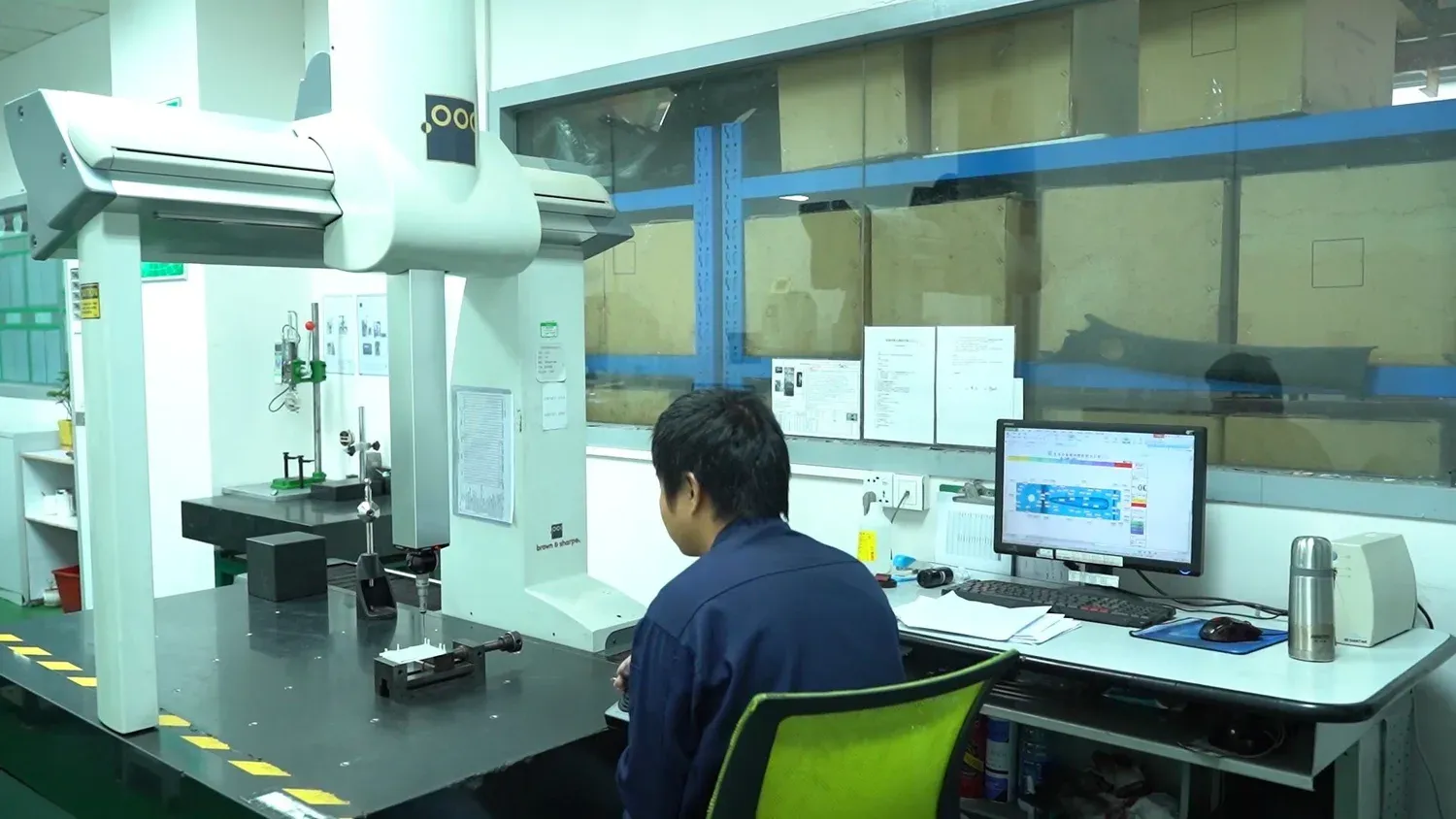
A tolerance a supplier cannot measure is a promise, not a specification. Our inspection room runs three fully automatic CMMs (coordinate measuring machines). Precision work is verified there, against the drawing, in a controlled environment, with the part fixtured on its datums — the same references the drawing declares. On request you can receive with a shipment: a CMM report with measured values against nominal for the called-out features; a dimensional report for the broader drawing; a first-article inspection (FAI) report when a new part or revision is being qualified; and material and finish certificates to close the traceability loop. Pre-shipment photos or video, too, if you want eyes on the parts before they travel.
Two habits make inspection work for you rather than against you. First, ask for the reports you will actually use, in the RFQ, so measurement is planned into the job → How to Get an Accurate CNC Machining Quote: What to Include in Your RFQ. Second, when a report shows a dimension at the edge of its band, treat it as information, not ammunition: a capable process centres its dimensions, and a supplier who shares real measured data is showing you the process, not a problem. Our quality system is ISO 9001:2015 certified (scope: Manufacturing of Hardware Molds and Parts), and the tolerance discipline in this guide is how that system shows up on your parts. The wider story of how we inspect and document is on our → Quality page.
A Five-Minute Drawing Review Before You Send
- Is there a general standard in the title block? If not, add "ISO 2768-mK unless otherwise specified" or expect that default.
- Are the genuinely functional interfaces — bearings, fits, seals, locators — individually toleranced? Those are your precision spend; confirm each one controls the behaviour you need.
- Is anything else tighter than ±0.13 mm (metal) or ±0.25 mm (plastic)? For each survivor of step 2, ask what fails if it relaxes to standard. Relax the ones with no answer.
- Do any precision dimensions apply after a coating? Mark them.
- Are datums declared, and do they match how the part assembles? If a hole pattern must meet a mating part, consider a position callout instead of tightened coordinates.
That is the entire discipline. Tolerance the interfaces, standardise the rest, and let the factory's process do what it is good at.
FAQ
What tolerance do you machine to if my drawing specifies none?
ISO 2768-mK general tolerances: medium class for linear dimensions, K class for geometrical ones. We confirm the default in the DFM review so there are no surprises at your incoming inspection.
What are your standard and precision tolerances?
Standard: ±0.13 mm (±0.005″) on metals, ±0.25 mm (±0.010″) on plastics. Precision: ±0.025 mm (±0.001″) on metals, ±0.05 mm (±0.002″) on plastics. Precision is quoted per feature — you pay for it only on the dimensions that carry the callout.
Why are plastic tolerances looser than metal ones?
Physics: plastics expand with temperature far more than metals, absorb moisture at different rates and flex under load. A plastic dimension that reads perfectly in a 20 °C inspection room will move in service. Tolerancing plastics like metals buys disputes, not function.
Does tightening a tolerance always raise the price?
Not always — relaxing from a very loose callout to standard (±0.13 mm on metal) usually changes nothing, because it sits inside normal process capability. Cost steps in when a callout leaves the standard tier: slower finishing passes, fresher tooling, CMM verification and higher scrap risk. The step is per dimension, so the count of tight callouts matters more than their presence.
Should I put tight tolerances on everything to be safe?
No. It raises cost, slows the job and generates rejections on dimensions that never affected function — without adding any safety. Tolerance the interfaces (fits, seals, locators), and let ISO 2768-mK govern the rest.
Do I need GD&T on my drawing?
Often not in full. Plain ± tolerances with clear datums cover most parts. GD&T earns its place for hole patterns that must meet a mating part, rotating features, sealing flatness and freeform surfaces. If you are unsure, send the drawing — our free DFM review flags where a GD&T callout would help and where one is costing you money for nothing.
How do tolerances interact with anodizing or plating?
Coatings add thickness — hardcoat anodizing adds a significant layer. If a dimension must be correct after finishing, write "applies after finish" on the drawing so machining targets the pre-finish size accordingly. Deciding this on paper is free; discovering it at inspection is not.
How will I know the parts actually meet the tolerances?
Ask for the documentation in your RFQ: CMM reports, dimensional reports and FAI are all available. Precision features are measured on our three fully automatic CMMs against the drawing's datums, and the measured values — not just pass/fail — are what you receive.
What tolerances can you hold on a 5-axis part?
The same tiers apply, and single-setup 5-axis machining often holds relationships between features (angles, positions across faces) better than multi-setup 3-axis work, because the part is never re-clamped. The process choice itself is covered in → 5-Axis vs 3-Axis CNC Machining: How to Choose.
Can you review my drawing before I finalise tolerances?
Yes — that is exactly what the free DFM review is for. Send the drawing with your RFQ and an engineer will flag over-toleranced dimensions and suggest where standard callouts suffice, within 24 hours, before you commit to the design or the order.
Get the Tolerance Right Before You Pay for It
The cheapest precision is the kind you never had to buy. Send us your drawing with your next → CNC Machined Parts enquiry: the DFM review is free, the quote comes back within 24 hours, and the tolerance advice comes from the people who will actually cut the metal. If a dimension deserves ±0.025 mm, we will hold it and prove it on a CMM. If it doesn't, we will tell you — and your quote will show the difference.